Circuit Design Project
Location: University of Toronto (2025)
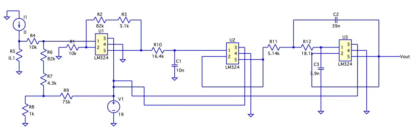
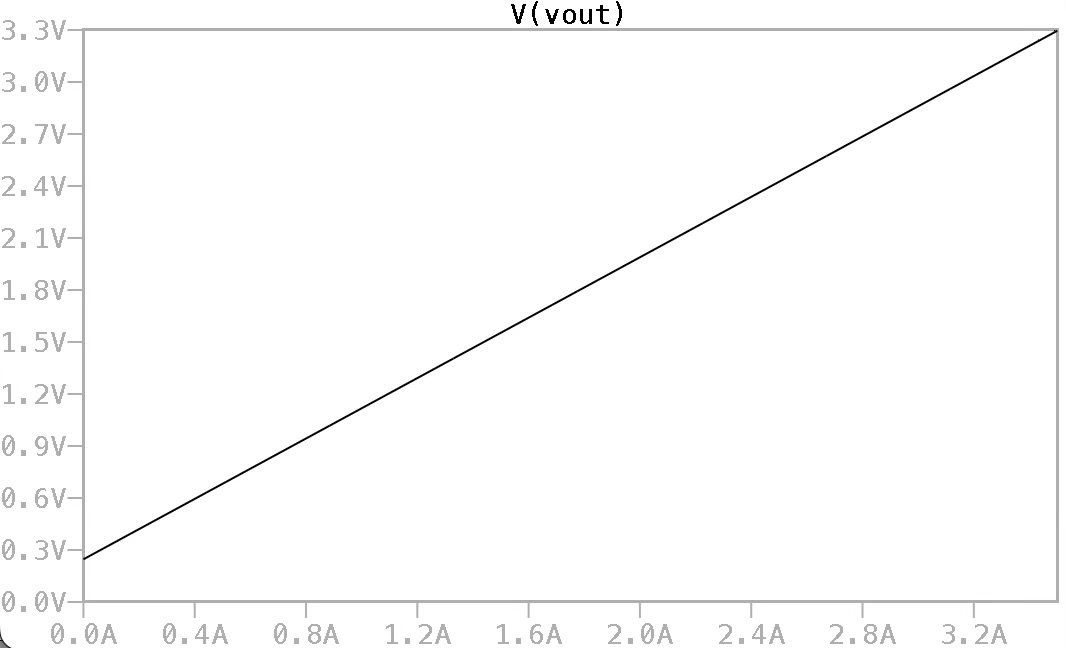
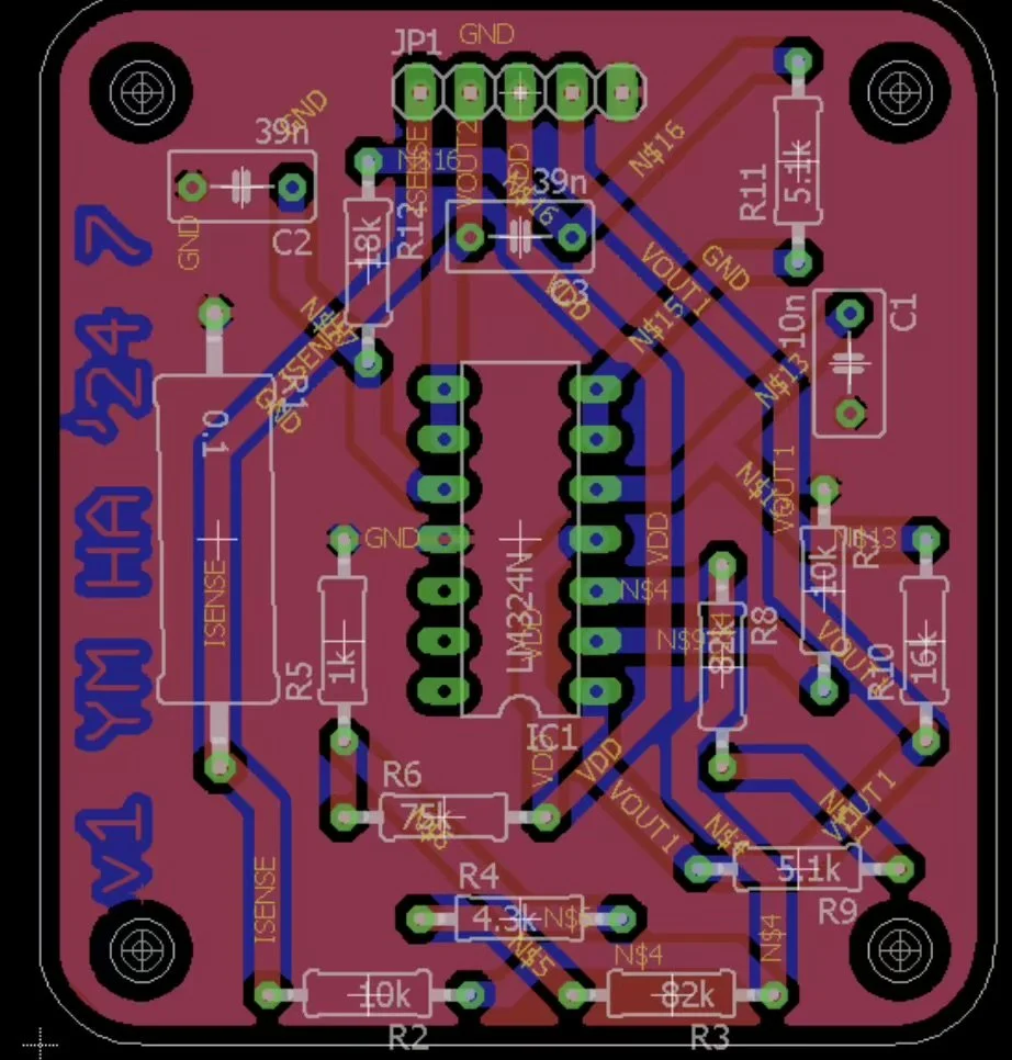
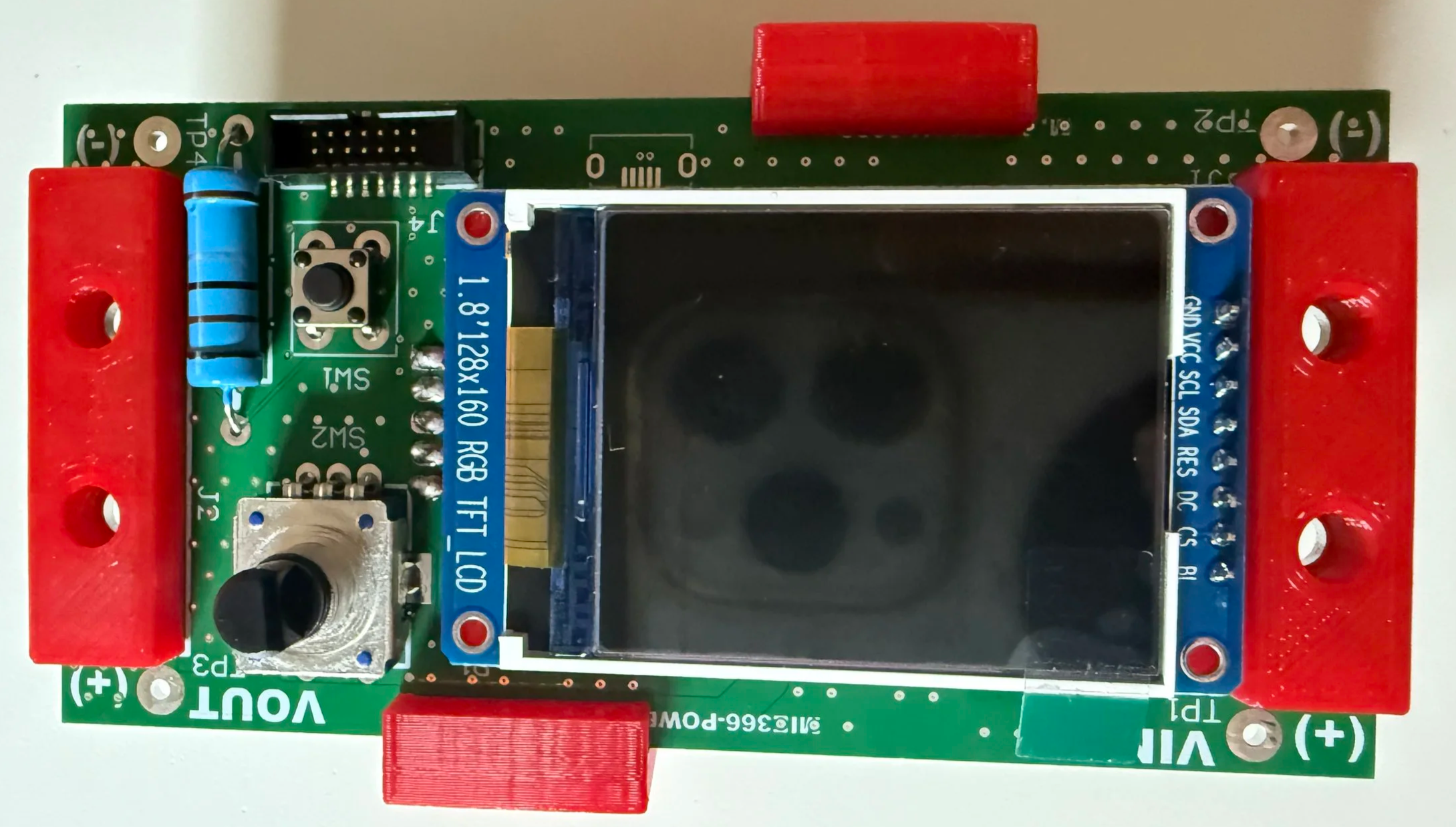
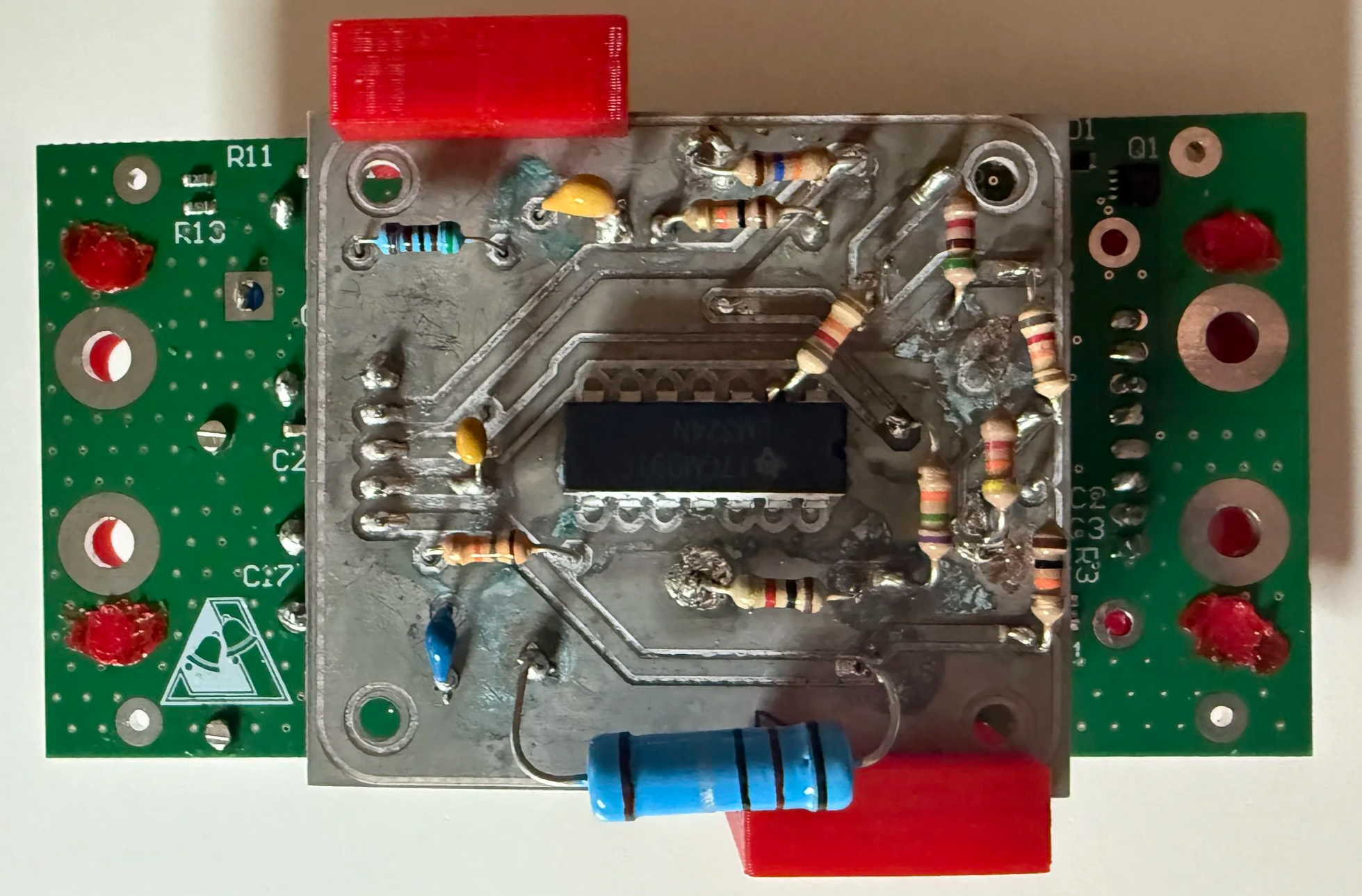
Descriptions: The objective of this design is to develop a current sense amplifier circuit that proportionally outputs a voltage ranging from 0.25V to 3.3V corresponding to a load current of 0A to 3.5A. The circuit was fully designed and assembled, including soldering components, mounting ICs, and testing the prototype board. The circuit is designed to meet input, output, and constraint specifications while optimizing performance for future applications. The input voltage generated by I_load and R_sense (0 to 0.35V) is amplified by a factor of 8.71 and shifted upward by an offset voltage of 0.25V, producing an output voltage range of 0.25V to 3.3V.
A filter is also incorporated with the following specifications:
Number of Op-Amps: 2
Cut-off Frequency: 1 kHz
Cut-off Frequency Attenuation: -0.1 dB
Gain: 0 dB
Stop Band Frequency: 5 kHz
Attenuation: -35 dB
Filter Response: 3rd order Chebyshev (0.10 dB ripple, 2 stages)
The design was developed using LTspice, and Eagle was used for schematic design and PCB layout.